

Locators / Sondes
Walkover locators and Magnetic Guidance Systems (ParaTrack MGS) — track the drill head from the surface, or steer it precisely on deep and inaccessible crossings.

What is a walkover locator?
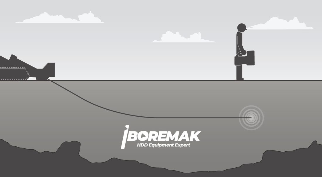
A walkover locator is the system that lets the drill head be tracked from above ground in horizontal drilling. A transmitter (sonde) placed inside the housing just behind the head emits an electromagnetic signal. Walking directly over the head (walkover) with the receiver (locator) in hand, the operator reads this signal and determines the head's position, depth, pitch and roll in real time.
The receiver transmits this data by telemetry to the remote display on the machine; so both the locator operator and the machine operator see the same information at the same time. In short, the walkover system is the eye and ear that lets the driver "see" underground.
How does it work?
The transmitter inside the housing emits a continuous signal at the selected frequency. Moving the receiver over the ground, the operator finds the signal's peak point; by aligning the front and rear locate points, they mark the head's horizontal position to centimetre accuracy. On the same screen, depth, pitch and roll are read.
In light of this information the driver steers the head in real time: locks onto the target, safely passes over/under existing utilities (power, gas, water, telecom) and keeps the planned grade. Accurate tracking means an on-target crossing, prevention of utility damage and faster completion.
Receiver and remote display
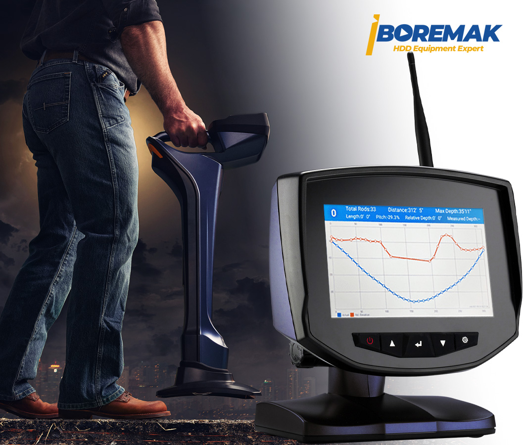
The system consists of two main parts: the handheld receiver (locator) moved around the site and the remote display at the machine. The telemetry link between them has a range of up to 1.2 km; thanks to 4 radio channels, data flows uninterrupted even in dense environments.
The remote display, with its 7-inch colour touchscreen LCD, clearly shows depth, pitch, roll and the signal graph; the crossing can be recorded with built-in data logging. This lets the locator operator and the driver work in perfect harmony.
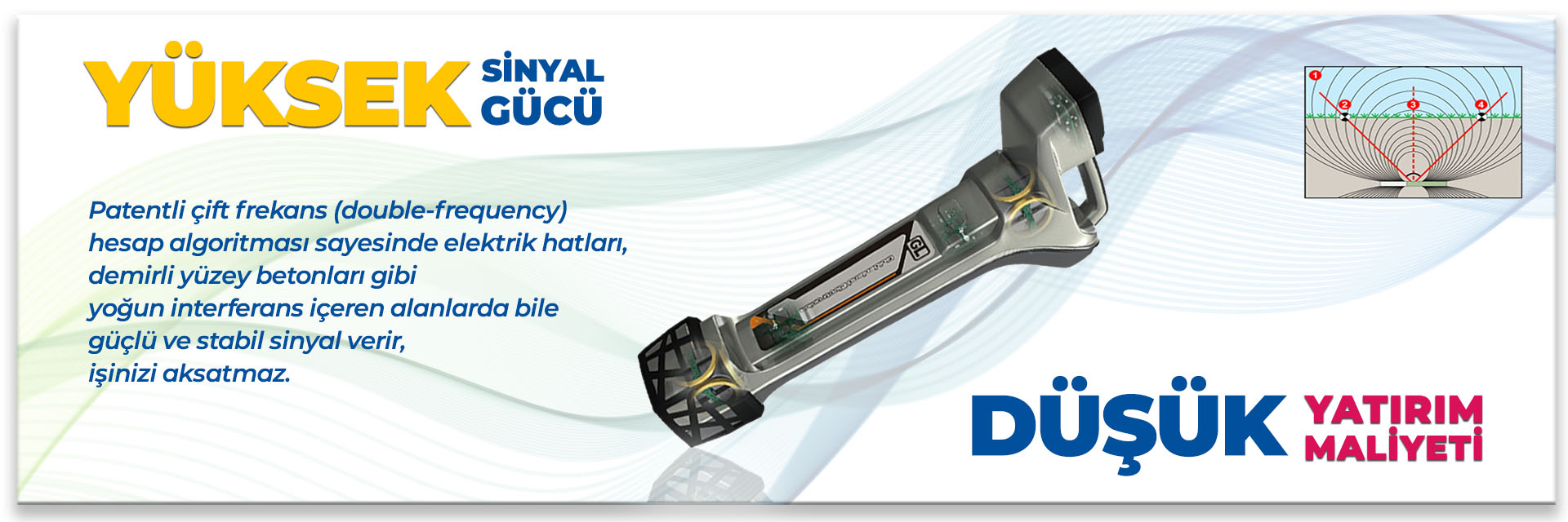
Multiple frequency and high signal strength — the GL difference
Where walkover systems struggle most is in sites with heavy interference: power lines, reinforced concrete, tram lines, dense utilities… Simple single-frequency locators lose the signal in these environments and read depth/position incorrectly.
GL locators, on the other hand, use 16 frequencies and a patented double-frequency calculation algorithm to evaluate multiple frequencies at once. This gives a strong, stable signal even in noisy areas and keeps the job moving. As a result the system provides reliable readings even at depths of up to 110 metres.
Its field benefit is direct: fewer failed/aborted crossings, more accurate targeting and less risk. On an HDD project, accurate locating is one of the highest-return investments.
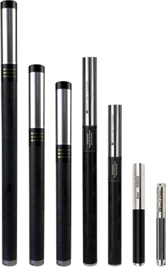
Transmitters (transmitter / sonde)
Transmitters are offered in different lengths and powers according to housing diameter, crossing depth and ground conditions. GL's ECHO series (ECHO50, ECHO50XF, ECHO60, ECHO70, ECHO75XF, ECHO90, ECHO110) and XNEEDLE cover a wide range of applications.
Short transmitters are ideal for narrow housings and shallow crossings, while high-power models provide a stable signal on deep and long crossings. Transmitter selection gives the most efficient result when planned together with the receiver, housing and crossing profile.
ECHO transmitters are built in a rugged stainless-steel body to withstand the impact, heat and vibration of drilling. High temperature tolerance (below 100°C) and IP67 protection class ensure safe operation in demanding field conditions. Their rechargeable lithium batteries offer long runtime depending on the power mode; with different battery options (21700 / 261020) you can choose between high power and long life as needed.
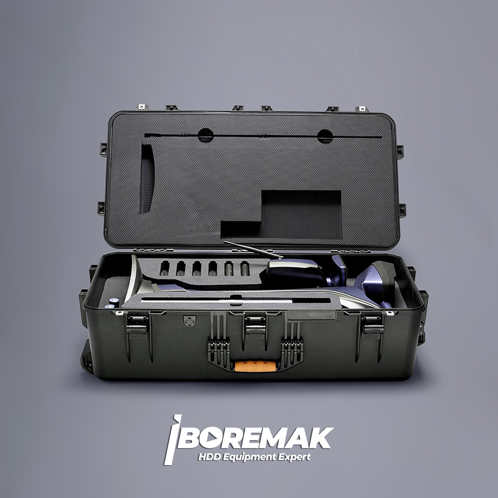
Carrying case and field durability
The receiver, display and transmitters are protected in a rugged carrying case resistant to impact and water. Thanks to the moulded foam interior, each part is carried safely in its own slot and set up quickly on site.
This ensures long life for the sensitive electronics and means equipment safety for a team constantly on the move.
Receiver (Locator) — Technical Specifications
| Frequency | 16 frequencies: K32 / K62 / 1 / 2 / 10 / 12 / 16 / 19 / 22 / 25 / 28 / 31 / 36 / 41 KHz |
|---|---|
| Compatibility | XNEEDLE, ECHO50, ECHO50X, ECHO50XF, ECHO60, ECHO75XF, ECHO70, ECHO90, ECHO110 |
| Telemetry | 4 radio channels, range up to 1.2 km |
| Protection class | IP65 |
| Battery | Rechargeable lithium, 12.5 V |
| Battery life | 50 hours |
| Dimensions | 71 × 16 × 33 cm |
| Weight | 3.7 kg |
Remote Display — Technical Specifications
| Telemetry | 4 radio channels, range up to 1.2 km |
|---|---|
| Data logging | Built-in (inbuilt data logging) |
| Screen | 7-inch colour LCD touchscreen |
| Battery | Rechargeable lithium, 12.5 V |
| Battery life | Up to 50 hours |
| Protection class | IP65 |
| Dimensions | 22 × 14 × 22 cm |
| Weight | 2.2 kg |
Transmitter (ECHO50XF) — Technical Specifications
| Frequency | 16 frequencies: K32 / K62 / 1 / 2 / 4 / 7 / 10 / 12 / 16 / 19 / 22 / 25 / 28 / 31 / 36 / 41 KHz |
|---|---|
| Power | 21700 rechargeable lithium battery / 261020 lithium battery |
| Battery life | 21700 (4.2 V): 6.5 h full power · 25 h normal power — 261020 (3.6 V): 15.5 h full power · 60 h normal power |
| Depth range | 40 m normal power · 50 m full power |
| Temperature | Below 100°C |
| Protection class | IP67 |
| Dimensions | φ3.2 × 38 cm |
| Weight | 0.7 kg |
| Battery voltage | 2.8 V – 4.2 V |
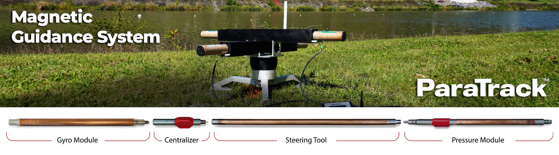





What is a Magnetic Guidance System (MGS / ParaTrack)?
A Magnetic Guidance System (MGS) is an advanced steering technology that, on horizontal drilling crossings where walkover is not possible, positions the drill head with high accuracy independently of the surface. Crossings under rivers, seas, harbours and highways; deep lines beyond walkover range; or sites where the surface is inaccessible due to traffic, water or dense utilities are the classic applications of this system.
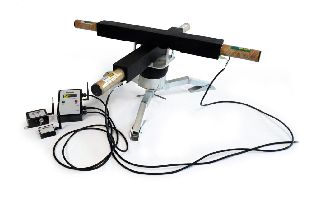
The ParaTrack system offered by Boremak is one of the most reliable MGS solutions in the industry. Its basic working principle is to create a controlled, known magnetic field along the crossing route and to have the precise sensors in the drill head (magnetometer + accelerometer) measure this field to calculate the head's position (X, Y, Z), azimuth, pitch and roll. Because the measurement is based on a known reference, the result is independent of depth and of surface magnetic interference. This makes MGS the standard solution for the toughest crossings where walkover is helpless.
How does it work? Probe and reference magnetic field
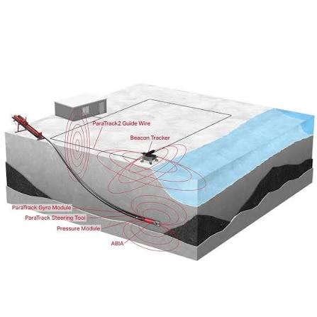
The heart of MGS is the probe (sensor unit) placed just behind the drill head and the reference magnetic field created on the surface or along the line. The probe measures both the artificial magnetic field and gravity with three-axis magnetometers and accelerometers; from this data the head's exact position and orientation in space are calculated.
In classic walkover, the receiver reads the signal by walking directly over the head, and accuracy drops sharply as depth increases. In MGS, position is solved against a mathematically known field; therefore centimetre-level accuracy is maintained even at depths of tens of metres and in places where you cannot walk on the surface.
Measurements are transferred in real time to the computer on the surface; the software shows the head's position live on the plan and provides instant correction data to the driver. So even on long, blind crossings the line advances without deviating from the designed route.
The surface-coil method
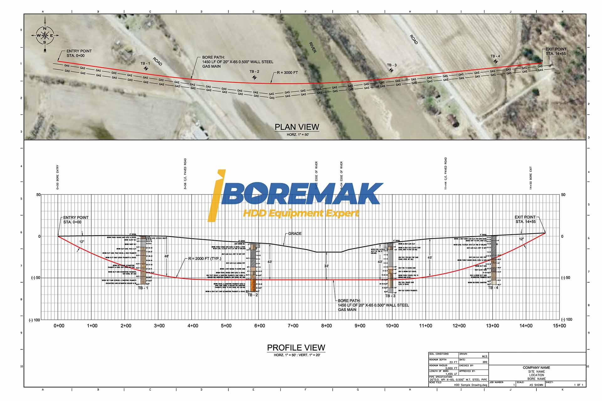
The most common MGS method is the surface coil. A pre-surveyed and coordinated cable-loop (coil) layout is laid over the crossing route, and current is passed through it to produce a known magnetic field. As the probe in the head measures this field, the system determines the head's exact position relative to the coil by triangulation.
Once the coil is precisely positioned, it forms a stable, reliable reference throughout the entire crossing; so deviation is minimised even on long, deep lines. The method provides very high accuracy on projects where surface access along the route is possible, such as fields, shallow water and above-water platforms.
The coil's shape and current are planned according to the project's geometry; multiple coils keep the reference continuous on long crossings.
The gyro method — direction independent of interference
On some sites it is not possible to lay a coil on the surface (heavy traffic, wide water crossings, inside steel pipe/casing) or the environment is magnetically very noisy. In these conditions gyro-assisted measurement comes into play. The gyro package determines direction (azimuth) by inertial measurement, without needing the Earth's magnetic field or a coil.
This lets the head's direction and position be tracked continuously even in environments where steel structures, rebar or other infrastructure create magnetic interference. Being immune to magnetic disturbances makes the gyro indispensable especially on critical, high-precision crossings.
The gyro method is often used together with the coil method as a complement; when the data from both methods are combined, the position solution is both more robust and more accurate.
When is MGS used? Its advantages
MGS is the most powerful solution wherever walkover falls short. Its main uses: deep crossings (beyond walkover range, usually ~15–20 m), long crossings (crossings that cannot be tracked from the surface, such as under rivers, harbours, bays and highways) and noisy/inaccessible sites (heavy traffic, power lines, reinforced concrete or above water).
The benefits it provides are clear too: high accuracy independent of depth, resistance to surface interference, minimised deviation on long lines, and the safe completion of crossings that are impossible with walkover.
In short, MGS makes it possible to lock onto the target on the most demanding HDD projects; a well-planned magnetic guidance secures both the success of the crossing and the safety of the surrounding existing infrastructure.
What is intersect drilling?
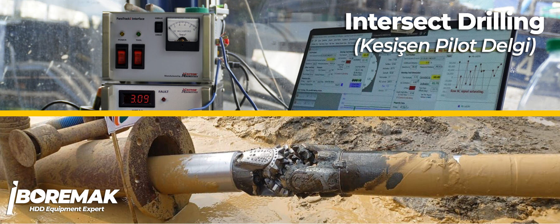
Intersect drilling is an advanced HDD technique used on very long crossings that exceed the capacity of a single machine. In this method, two separate machines start drilling simultaneously from the two ends of the crossing, and the goal is for the two pilot holes to intersect (meet) each other underground at a predetermined point.
This meeting can only be achieved with millimetric precision using a powerful magnetic guidance system. In ParaTrack, one head carries a known magnetic-field source (coil/beacon) while the probe in the other, oncoming head measures this field and is steered toward the target; as the two heads approach, the system continuously corrects deviation to achieve a flawless intersection.
The intersect method reduces total risk on very long river and sea crossings by drilling shorter, more controlled bores from each side, allowing larger diameters and much longer distances. This makes it the indispensable method for the world's most ambitious infrastructure crossings.
Intersect and long crossings with ParaTrack
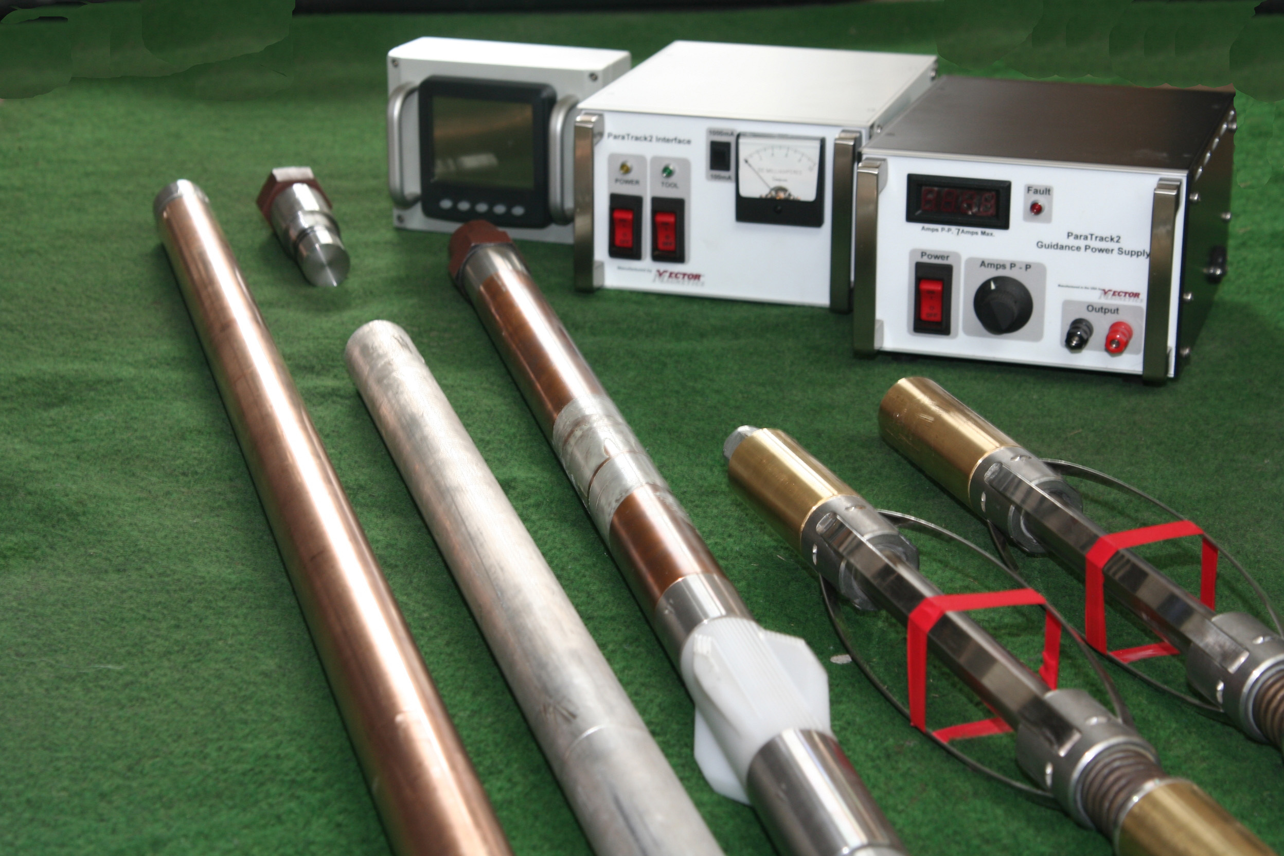
ParaTrack provides the reference system that brings two drilling teams together on a single target in intersect applications. The head on one side carries the source coil, and the head on the other side carries the probe; the system calculates the relative position between the two heads in real time and provides instant correction data to the drivers.
This approach makes crossings of a length unreachable by a single machine (kilometres) feasible and provides a more manageable drilling process from both sides.
Share your project's length, depth, ground profile and crossing conditions; let's determine together which of the walkover, surface-coil, gyro or intersect methods is most suitable and the equipment set required.
Call us for stock and price information on the locator, transmitter and MGS solution best suited to your project!
+90 850 888 3585